If you’re reading this, chances are you’ve been troubleshooting a nagging issue with your planer mill: your tools keep breaking before their expected lifespan, throwing off production schedules, increasing replacement costs, and leaving your team wondering what’s gone wrong. As a supplier of Planer Type Boring and Milling Machines, I’ve spent thousands of hours working with shops just like yours, walking through their workflows, inspecting their machines, and dissecting hundreds of failed tools to get to the root cause. This isn’t a random problem—and it almost never has a single easy fix. Let’s break down the most common reasons this happens, how to spot them, and what you can do to avoid it. Planer Type Boring and Milling Machines
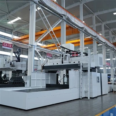
First, let’s clarify one thing: a “planer mill tool” here refers to the cutting tools used on planer-type boring and milling machines—inserted carbide end mills, face mills, boring bars, and even the larger multi-tooth tools designed for heavy, deep cuts on large workpieces like diesel engine blocks, turbine housings, or heavy structural steel beams. These tools aren’t made to break every few days; their standard lifespan is measured in hours of cut time, not days or weeks. So when you’re seeing frequent breakage, it’s almost always a mismatch between your tool, your machine, or your workflow—not a flaw in the tool itself.
Let’s start with the most frequent culprit: machine stiffness and rigidity, specifically the way your planer mill is set up for a job. Planer mills are heavy-duty machines, but their rigidity isn’t uniform everywhere. A common mistake we see is shops extending tooling much further out from the machine’s spindle or the tool holder than recommended, or clamping large workpieces loosely on the machine’s worktable. Let’s break this down: when a tool extends more than 3 times its diameter, it creates a lever effect. For example, a 1-inch diameter end mill extended 4 inches out from the holder will flex under cutting pressure, not just at the tip but along the length. Every time the tool flexes to make a cut, it snaps back, creating micro-fatigue at the base of the tool or at the insert seat. Over dozens of cuts, that micro-fatigue turns into a crack, and suddenly the tool breaks mid-operation.
We once worked with a shop that was machining 12-foot long steel beams for bridge construction on a 5-meter planer mill. They had extended a 1.5-inch diameter face mill 6 inches out to reach the far edge of the beam, rather than repositioning the worktable. They saw a tool break every 2 to 3 hours of run time, costing them $1,200 per tool and 4 hours of downtime per incident. When we adjusted the tool projection to 3.5 inches (right at the 3x diameter limit) and reindexed the workpiece to center it under the tool, their tool life jumped to 18 hours per tool. That’s a 5x improvement, all from a small adjustment that didn’t require buying new equipment.
Workpiece clamping is another part of rigidity that’s often overlooked. Large workpieces don’t just stay perfectly still during milling—even a tiny shift of a few thousandths of an inch can create a moment of extreme cutting force that snaps a tool. Planer mills rely on T-slot clamps, step blocks, and sometimes vacuum hold-downs for thinner workpieces, but many shops skimp on clamping points to save setup time. If you’re machining a 10,000-pound turbine housing with only two clamps on each end, it’s going to rock or shift slightly when the tool plunges into the metal. That sudden, uneven force doesn’t just ruin the cut—it sends a shock through the tool shank that can break it instantly or create a hidden crack that leads to later breakage. We recommend a minimum of one clamp every 2 feet for workpieces longer than 6 feet, and never clamping only at the ends—add clamps along the edges where the tool is cutting to keep the workpiece stable.
Next, let’s talk about cutting parameters, which are the settings you input into your planer mill’s control: spindle speed, feed rate, and depth of cut. These are almost always mismatched for the tool material or the workpiece, and it’s the single most common mistake we see across all types of shops, from small job shops to large automotive parts manufacturers. Let’s take carbide tools, which are the most common for planer mills. Carbide is hard, but it’s brittle—especially if it’s a general-purpose carbide grade, not one designed for heavy milling. If you run a carbide tool at a spindle speed that’s too high, the cutting edges heat up too fast and can’t dissipate the heat, leading to thermal fatigue and chipping. If the feed rate is too low, the tool is rubbing against the workpiece instead of cutting, which creates even more heat and wears the tool down prematurely. If the depth of cut is too high, the tool is taking too large a bite with every tooth, creating more force than the tool is designed to handle.
We worked with a heavy equipment manufacturer that was machining cast iron engine blocks on a 6-meter planer mill. They were using a 2-inch face mill with 10 carbide inserts, running at 120 RPM and 0.005 inches per tooth (IPT) feed. Their tools were breaking after an average of 1 hour of use. We checked their parameters and found that the manufacturer’s recommended feed rate for that tool in cast iron was 0.008 to 0.012 IPT. When we adjusted the feed rate to 0.009 IPT and the spindle speed to 100 RPM (a 17% reduction, which matched the tool’s heat resistance rating), their tool life jumped to 7 hours, and breakage dropped to less than one per month. That’s another big win, all from tweaking settings.
A related cutting parameter mistake is climb vs. conventional milling. Most planer mills are designed for one or the other, and mixing them up is a quick way to break tools. Climb milling is when the tool rotates in the same direction as the worktable feed, which reduces cutting force and is better for most heavy milling jobs. Conventional milling is when the tool rotates opposite to the feed, which is better for thin workpieces or workpieces that can’t be clamped tightly. If you run climb milling on a workpiece that’s prone to shifting, you’ll get unexpected force spikes, but if you run conventional milling on a rigid setup, you’ll have more friction and tool wear. Many newer planer mills have a setting that automatically switches between the two based on workpiece material and rigidity, but if your machine is older (pre-2015, roughly), it’s something you have to adjust manually.
Another issue that’s easy to miss is tool holder condition. A tool is only as strong as its connection to the machine’s spindle. If your planer mill’s spindle has worn taper holes (usually BT or HSK tapers, depending on the machine), or if your tool holders have worn tapers, loose retention knobs, or contaminated shanks, the tool isn’t seated securely. When you cut, the holder can shift slightly, creating excessive vibration that eventually breaks the tool. Vibration is a silent killer in milling—you might not notice a small vibration when you watch the machine run, but over time, it causes cyclic stress that cracks the tool from the inside out.
We recently had a customer with a 2012 planer mill who was breaking 1-inch boring bars every 10 to 15 pieces. We inspected his tool holders and found that his BT50 taper holders had a small amount of rust and debris in the taper holes, which made the tool seat only 80% of the way in. When we cleaned the tapers, replaced the retention knob (which had worn threads), and rebalanced the holders, his boring bars lasted 80 pieces each. That’s a huge difference from a small, overlooked part maintenance task. We recommend inspecting tool tapers for rust, debris, or wear every 50 hours of operation, and replacing retention knobs every 10,000 cycles or so.
Tool material and grade mismatch is another common issue, especially when shops try to save money on tooling by buying cheaper, generic inserts instead of ones matched to their workpiece. Planer mills often machine hard materials: stainless steel, alloy steel, cast iron, even titanium. Generic carbide inserts work for soft materials like aluminum or mild steel, but they’re too brittle and wear too fast for hard alloys. If you use a general-purpose insert for machining 4140 alloy steel, the insert will chip or break because it’s not designed for the high temperatures and cutting forces that come with hard materials. We also see shops using uncoated inserts for heavy roughing, when coated inserts (specifically TiN, TiCN, or TiAlN coatings) are necessary to reduce friction and heat. The coating adds a thin, hard layer that protects the cutting edges from wear, so skipping it to save a few cents per insert is a false economy.
Sometimes, the issue is not with the tool or the machine, but with how you’re handling or storing the tools between uses. Caring for tools might seem trivial, but dropping a tool on the shop floor, storing inserts loose in a drawer instead of in organized cases, or using a dirty tool box that has debris scratching the tool shank can all lead to breakage. A dropped tool might look fine on the outside, but it can have a micro-crack at the base of the shank that will show up when you start machining. We’ve seen shops that only replace tools after they break, only to find that half of their tools in inventory have hidden damage from being dropped. Organized tool storage, with individual slots for each tool and insert case, is a small investment that pays off in reduced breakage.
Now, let’s talk about machine-specific factors, since we’re Planer Type Boring and Milling Machines suppliers. Many planer mills have unique features that, when used incorrectly, lead to tool breakage. For example, some larger planer mills have a cross rail that can sag over time, especially if it’s a older machine or has a heavy workpiece mounted. Sag in the cross rail means the tool is not perfectly perpendicular to the workpiece, so one side of the tool is taking a larger cut than the other. That uneven cut creates uneven force, which can bend or break the tool. Regular cross rail alignment checks (every 6 months, or after moving the machine) fix this issue. We include a cross rail alignment tool with every new planer mill we sell, and offer annual maintenance check-ups for customers to catch sag before it causes tool breakage.
Another machine-specific issue is spindle speed range. Planer mills are designed for heavy, slow cutting, but some older machines have a limited spindle speed range, so if you’re machining a hard material, you might have to run a slightly lower speed than ideal, but if you push it beyond the machine’s rated range, you’ll put excessive stress on the spindle and the tool. We design our planer mills with a wide, variable spindle speed range that matches the needs of heavy milling, so our customers don’t have to compromise on speed to get the power they need.
Let’s wrap this up with actionable steps you can take right now to reduce tool breakage: First, check your tool projection—keep it to 3x the tool diameter or less, and reposition workpieces instead of extending tools further. Second, audit your clamping setup—add clamps every 2 feet for workpieces over 6 feet, and test for shifts by tapping the workpiece lightly before starting a cut. Third, adjust your cutting parameters: confirm your spindle speed and feed rate match the tool grade and workpiece material, and use climb milling for rigid setups. Fourth, inspect your tool holders and spindle tapers for wear, debris, or loose knobs, and replace worn parts as needed. Fifth, invest in tool storage to prevent drops and damage, and match your tool grades to the materials you’re machining.
If you’ve tried all these steps and you’re still seeing frequent tool breakage, it might be time to look at your planer mill’s performance. Many shops don’t realize that their machine’s rigidity or spindle power is not matched to the tools they’re using, or that minor machine misalignments are causing the issues. As a Planer Type Boring and Milling Machines supplier, we specialize in working with shops to troubleshoot these exact problems—we can help you inspect your machine, adjust your setup, and recommend the right tools and machine features to reduce breakage and boost your production.
If you’re ready to stop wasting money on broken tools and missed production time, get in touch to discuss your specific workflow, machine, and tool challenges. We’ll work with you to find a solution that fits your needs, no matter the size of your shop.
CNC Gantry Boring Mill References
- Tool Materials and Cutting Parameters for Milling Operations, Manufacturing Process Research Journal, 2021
- Rigidity Analysis of Planer-Type Milling Machines, International Journal of Machine Tools and Manufacturing, 2018
- Tool Holder Maintenance Best Practices for Heavy Machining, Industrial Tooling Association Report, 2020
- Climb vs. Conventional Milling: Effect on Tool Life, Journal of Manufacturing Engineering, 2019
5Axis (Shandong) CNC Equipment Co., Ltd.
As one of the most professional planer type boring and milling machines manufacturers and suppliers in China, we also accept customized orders. Please feel free to buy cheap planer type boring and milling machines for sale here from our factory. For price consultation, contact us.
Address: No.2000, Beixin West Road, Jinghe Street, Tengzhou City, Zaozhuang City, Shandong Province
E-mail: summer@good5axis.com
WebSite: https://www.china5axis.com/
